Can custom hydraulic hoses Be Made with Different Hose Fittings?
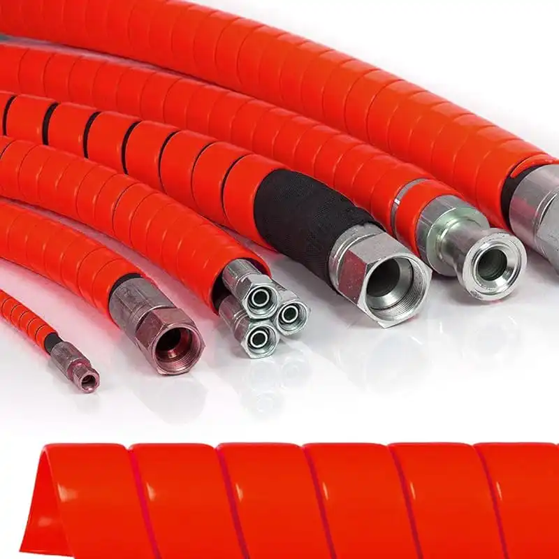
Yes. A custom hydraulic hose can be built with different fittings on each end, provided the hose, fitting stem, ferrule, thread, seal, and crimp specification are approved for the intended pressure and fluid. Common combinations include JIC 37°, ORFS, NPT, BSPP, BSPT, DIN metric, and SAE flange ends. Many industrial hydraulic hoses are designed around a 4:1 minimum burst-to-working-pressure ratio under standards such as SAE J517 or ISO 18752. A 3,000 psi hose, for example, may require a minimum burst pressure near 12,000 psi. Mixing visually similar fittings without verified compatibility can reduce assembly reliability even when the threads appear to fit.
A custom hydraulic hose is normally specified as a complete assembly rather than a hose tube with two interchangeable connectors. The hose bore, reinforcement layers, fitting insert, ferrule, crimp diameter, thread form, and sealing surface all affect how the assembly handles pressure. SAE J517 has been used for decades to define construction and performance requirements for widely used hydraulic hose types, while ISO 18752 groups hoses by pressure class and performance level rather than relying only on reinforcement construction. In many common specifications, burst pressure is at least 4 times rated working pressure, so a hose rated at 4,000 psi may be expected to withstand about 16,000 psi during qualification testing before rupture.
Different fitting styles can be placed on opposite ends because the fluid path does not require both ports to use the same connection standard. A machine may have a JIC female swivel connection at a valve and an ORFS connection at a cylinder, or an NPT male connection at one end and a BSPP connection at the other. This arrangement is common when equipment contains pumps, valves, motors, or cylinders sourced from different manufacturers.
The connection should be selected from the port outward: identify the port standard first, then the fitting, then confirm that the fitting series is approved for the hose being used.
That sequence matters because thread diameter alone cannot identify a fitting reliably. A 1/2-inch nominal connection can belong to several thread systems with different pitches, seat angles, and sealing methods, and the wrong combination may thread together for several turns before binding or leaking.
JIC fittings are common on North American mobile and industrial equipment and use a 37° metal flare for sealing. SAE 45° flare fittings also exist, so the two should not be identified by appearance alone. A 37° seat and a 45° seat differ by 8°, enough to prevent correct surface contact even when thread dimensions appear compatible. ORFS fittings use an elastomeric O-ring compressed against a flat face, making them common where leakage control and vibration resistance are important.
NPT connections work differently. Their tapered threads create increasing interference as the connection is tightened, usually with an appropriate thread sealant. BSPT also uses a tapered thread, while BSPP normally uses a parallel thread combined with a separate sealing surface or seal. Mixing NPT and BSP threads is unsuitable because their thread forms and pitches differ. For example, a 1/2-inch NPT connection uses 14 threads per inch, while a 1/2-inch BSP connection also has 14 threads per inch but uses a different thread angle: NPT is 60°, compared with 55° for BSP.
Metric fittings introduce another identification step because thread diameter and pitch both need to be checked. Metric hydraulic connections may use DIN 24° cone systems, metric O-ring designs, or other sealing arrangements. Two fittings may both be marked M18 yet require different pitches or sealing geometry. A technician normally checks the outside diameter with calipers, measures thread pitch with a gauge, identifies the sealing face, and confirms whether an O-ring is present before ordering the replacement.
SAE flange connections are more common as hose bore and flow demand increase. SAE J518 flange systems are widely used on pumps, motors, cylinders, and larger hydraulic lines, particularly where a large threaded connection would be difficult to install. Code 61 and Code 62 flanges are not interchangeable simply because the outside appearance is similar. Code 62 is generally intended for higher-pressure applications and uses different dimensional requirements.
| Fitting family | Typical sealing method | Common application |
|---|---|---|
| JIC | 37° metal flare | Mobile and industrial hydraulics |
| ORFS | Face O-ring | High-pressure, low-leakage systems |
| NPT | Tapered thread | North American equipment |
| BSPP | Parallel thread with seal | European and international machinery |
| BSPT | Tapered thread | General hydraulic connections |
| DIN metric | 24° cone / O-ring designs | European equipment |
| SAE flange | O-ring flange face | Large-bore and high-flow circuits |
Selecting the connection family still does not determine whether a fitting can be crimped onto a particular hose. A fitting stem designed for one hose series may have a different insertion diameter, serration profile, or ferrule length from a fitting that looks almost identical. Crimp tolerances are often controlled within fractions of a millimeter, and manufacturers publish specific finished crimp diameters for each hose and fitting combination.
A crimp that is too large can leave insufficient grip on the reinforcement; a crimp that is too small can damage the tube, fitting stem, or wire reinforcement.
Pressure performance depends on that compression. Under SAE and ISO qualification methods, hydraulic assemblies are subjected to pressure, leakage, burst, and impulse tests. Some hose categories are expected to survive hundreds of thousands of pressure cycles, while higher-performance classes under ISO 18752 can require up to 1,000,000 impulse cycles depending on the grade and temperature category.
Hose construction also limits which fittings are suitable. A compact one-wire braided hose does not have the same wall thickness or reinforcement structure as a two-wire braided hose or a four-spiral high-pressure hose. Even when all three have the same nominal inside diameter, their outside diameters and fitting requirements can differ. A fitting designed around a 12 mm wall structure cannot simply be treated as suitable for another hose because both products carry the same dash size.
Pressure must therefore be checked at assembly level. A custom hydraulic hose rated for 5,000 psi does not create a 5,000 psi assembly when a fitting, adapter, flange, or port has a lower allowable pressure. The permitted assembly pressure is limited by the lowest-rated component. Hydraulic systems also experience short pressure peaks that may exceed the gauge pressure seen during steady operation, which is one reason hose qualification includes cyclic and burst testing rather than only a single static pressure check.
Temperature adds another limit. Many standard petroleum-oil hydraulic hoses operate in ranges around -40°C to 100°C, while certain constructions are rated to 125°C or higher. The fitting body may tolerate those temperatures, but the tube compound, cover, and O-ring material may not respond equally to heat. At elevated temperature, elastomers can harden faster and hydraulic oil oxidation can also accelerate.
Fluid type changes the material requirement again. Petroleum-based oil is common, but equipment may use water-glycol fluids, phosphate-ester fluids, biodegradable hydraulic fluids, or synthetic formulations. Compatibility should be checked against the hose inner tube and any O-rings in the fitting. An ORFS connection, for example, depends on the face O-ring for sealing, so selecting an unsuitable elastomer can cause swelling, hardening, or loss of sealing force even though the steel fitting itself remains undamaged.
Material selection becomes more important in corrosive environments. Carbon-steel fittings with protective plating are widely used on construction, agricultural, and factory equipment. Stainless-steel fittings are more common around saltwater, washdown areas, offshore equipment, chemical processing, or food production. Stainless steel normally costs more, so the application environment should justify the material rather than using it automatically.
Fitting angle also affects service life. Straight, 45°, and 90° ends are widely available, and choosing between them changes how the hose leaves the port. A hose forced into a sharp bend immediately behind the ferrule places repeated stress close to the rigid fitting. Manufacturers therefore specify minimum bend radius; depending on hose size and construction, that radius may range from under 100 mm for smaller hoses to several hundred millimeters for larger spiral hoses.
Two elbow fittings create an additional manufacturing requirement: angular orientation. If a hose has a 90° elbow at each end, the relationship between the two elbows may need to be set at 0°, 45°, 90°, 180°, or another specified angle. An orientation error of only several degrees can create unwanted twist after installation on a short, rigidly routed assembly.
Twisting should not be corrected by forcing the hose into position. SAE installation guidance has long emphasized routing hoses without torsional stress because reinforcement wires are designed primarily to contain internal pressure, not sustained twist. Where equipment movement is involved, enough hose length should be provided to accommodate travel without pulling on the fittings at full extension.
Replacement work needs the same level of measurement. Copying overall length alone is not enough. A replacement specification should record hose size, hose type, fitting at end A, fitting at end B, thread diameter, thread pitch, sealing style, elbow angle, elbow orientation, and the method used to measure overall assembly length. A difference of 25 mm can be significant in a short assembly installed between two fixed ports.
-
Measure the thread diameter with calipers rather than estimating it visually.
-
Use a thread-pitch gauge for inch and metric threads.
-
Check whether the seal is made by a flare, cone, O-ring, bonded washer, tapered thread, or flange.
-
Record both fitting angles before removing a hose with two elbows.
-
Confirm rated working pressure and fluid compatibility before fabrication.
-
Inspect the finished crimp against the manufacturer's published diameter.
Manufacturing traceability is also useful for fleet and industrial maintenance. Recording the hose series, fitting part numbers, assembly date, and technician or production batch makes later replacement easier. SAE J517 dates back to long-established North American hose practices, while ISO 18752 was introduced in 2006 and later revised to provide pressure-based hose classifications suited to modern hydraulic systems.
A mixed-fitting assembly can therefore be entirely normal. A JIC-to-ORFS hose, metric-to-JIC hose, BSPP-to-flange hose, or straight-to-90° assembly may remove the need for an extra adapter and shorten the installed connection. Removing one adapter also removes two threaded interfaces that otherwise require assembly, inspection, and future maintenance.
The limitation is compatibility rather than fitting variety. Hose manufacturers qualify particular hose and fitting families together because stem geometry, ferrule design, reinforcement compression, impulse resistance, and pull-off strength work as one system. With rated components, verified crimp data, correct thread identification, suitable seals, proper bend radius, and assembly pressure based on the lowest-rated part, a custom hydraulic hose can use different fittings on each end while meeting demanding mobile and industrial hydraulic requirements.